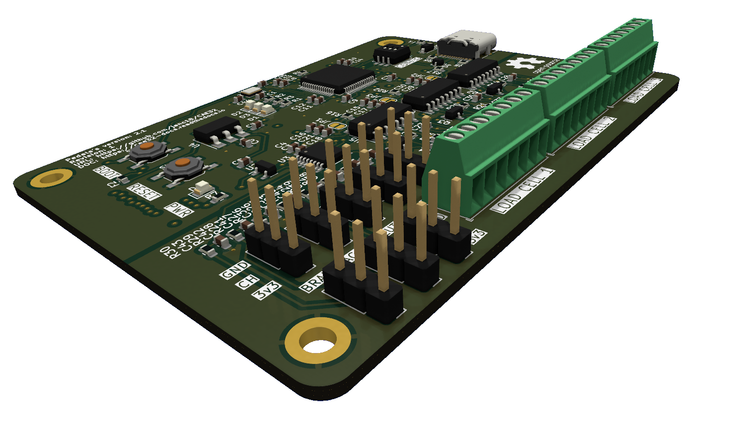
Pedals PCB
Version: 2.1 Revision: 1
Features
- 8 Analog Inputs
- 3 Inputs for Load Cells
- Extension Port
- UART (For firmware updates or other purposes)
- 2 x SPI
- CAN (No transducer included)
- USB-C port for communication with PC and firmware updates
PCB Purpose
It is used to capture the position of the pedals with its 8 analog channels and support for load cells.
Electrical Schematic
Key Components
| Name | Quantity | Datasheet |
|---|---|---|
| STM32F072RBT6 | 1 | Link |
| ADC128S102 | 1 | Link |
| HX711 | 3 | Link |
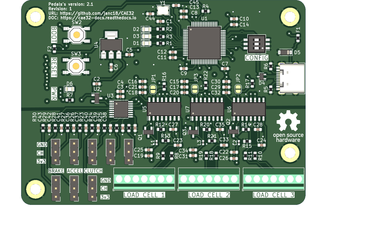
Analog Inputs (ADC128S102)
To acquire the position of the sensors (potentiometers, Hall effect, etc.), the ADC128S102 IC is used, which is an 8-channel multiplexer that integrates a 12-bit ADC, providing a resolution of 4096 positions.
The PCB has labels such as ACCEL, BRAKE, CLUTCH and CH.
By default, ACCEL, BRAKE, CLUTCH correspond to the default sensor inputs, while the row above are the channels that can be used for any other purpose

| Label Name | Meaning |
|---|---|
| 3v3+ | 3.3v Output |
| CH | Analog sensor |
| GND | Ground |
To provide a more stable reference voltage, a 3.3V voltage reference integrated circuit REF3033 is added to the PCB, which allows for more stable readings.
Precautions
It is your responsibility to verify the connections of the sensors you intend to use
-
There is no protection against reverse polarity (reversed connection of GND and 3v3).
-
There is no protection against overload.
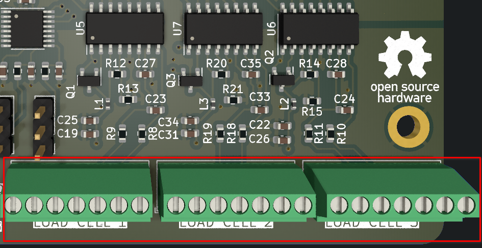
Load Cells
It supports 3 load cells.
The design is based on the diagram created by Digikey, with an added modification explained in the diagram. SparkFun_HX711_Load_Cell_V11
Design by: N.Seidle
License: CC BY-SA 4.0
Each of the ports for the load cells is labeled, and they have typical symbols, but it all depends on the chosen load cell.
For more information, I recommend referring to the electrical diagram here.
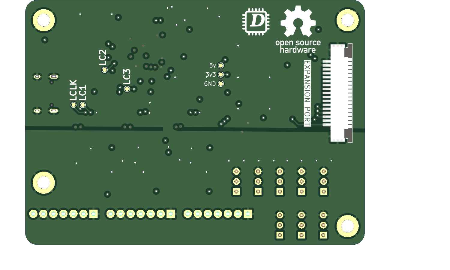
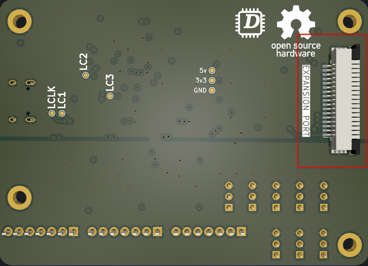
Expansion Port
The expansion port are connected to communications buses(UART,SPI and CAN), than can be used for debugging purposes or to expand the capabilities.
Device Mode (USB-C)
It allows the STM32F072RBT6 Microcontroller to act as a HID (Human Interface Device), which means it will be recognized as a joystick by the PC.